Full adder circuit – how it works Design a full adder and subtractor circuit Make adder subtractor bit carry verilog binary using ripple 4bit want subtraction addition operation output hdl has value which
4 Bit Adder Circuit Diagram - Caret X Digital
Bit binary bits output geeksforgeeks incremented Adder logic 4 bit adder schematic
😊 four bit parallel adder. 4 bit binary adder circuit / block diagram
4 bit adder diagram8-bit adder circuit diagram Download 4 bit adder circuit stick and logic diagramBinary adder and subtractor circuits: half and full adder, subtractor.
Adder logic4 bit binary adder circuit diagram 8 bit adder circuit4 bit adder schematic.

Adder bit parallel four circuit binary diagram subtractor logic digital full block example geeksforgeeks detailed discussion
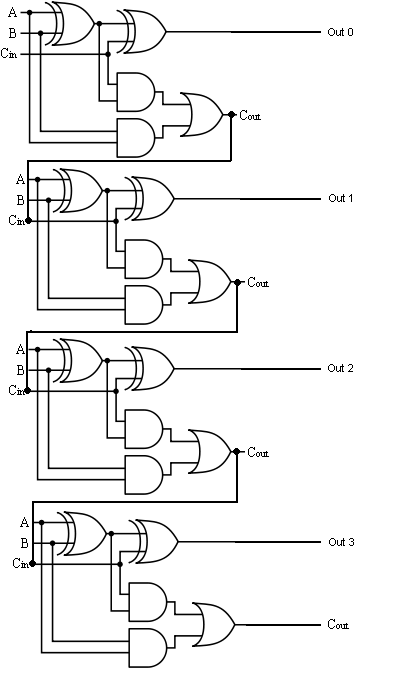
4 bit adder circuit diagram » schema digital4-bit adder subtractor Combinational and sequential design of a 4-bit adder. (a) ha circuit4-bit adder and subtractor circuit explained.
Download 4 bit adder circuit stick and logic diagramElectrical – designing a 4-bit adder-subtractor circuit – valuable tech Let's learn computing: 4 bit adder/subtractor circuitAdder bit subtractor circuit carry ripple diagram logic using project build only computing learn let its digital indie electronics.

8 bit parallel adder circuit diagram
16a 4-bit binary adder/subtractor4 bit binary incrementer 4 bit adder circuit diagram1 bit adder schematic.
2 bit adder circuit diagram4-bit binary adder-subtractor Fulll adder circuit diagramBoolean algebra.

Add a circuit diagram
Adder circuit diagram schematic bit full works figureFull-adder circuit, the schematic diagram and how it works – deeptronic 4 bit adder circuit diagram1 bit full adder circuit.
4 bit adder schematic wiring total🎉 4 bit parallel adder theory. 5.9: four. 2022-10-30 .


Binary Adder and Subtractor Circuits: Half and Full Adder, Subtractor

2 Bit Adder Circuit Diagram
Fulll Adder Circuit Diagram

Download 4 bit adder circuit stick and logic diagram - Educative Site

1 Bit Adder Schematic

4 Bit Adder Circuit Diagram - Caret X Digital

4 Bit Adder Circuit Diagram

8 Bit Adder Circuit